Technical details — the 24-round wall
Why the wall is put together the way it is: the pin budget, the carrier PCB, how the 24 clocks are numbered, the sync protocol, power, memory, and how the YAML files compose. Reference material — you do not need any of it to build one, and all of it to change one.
See also Assembly, wiring and flashing and the build’s front page.
Per-board pin budget
One XIAO ESP32-S3 driving three GC9A01A panels, and what that leaves free. The
PCB is the authority here: every net on the board matches a substitution in
common_base_esp32_s3_xiao.yaml, and the
YAML follows it, not the other way round.
| Pin | GPIO | PCB net | YAML | Used by | Note |
|---|---|---|---|---|---|
| D0 | 1 | — | free | ||
| D1 | 2 | UART |
sync_pin |
sync bus | clean: no strapping function, no ROM UART |
| D2 | 3 | RESET |
reset_pin |
LCD reset, all three panels | strapping pin (JTAG source select); fine as a reset output, don’t hold it low at boot |
| D3 | 4 | DC |
dc_pin |
LCD DC, all three panels | |
| D4 | 5 | CS_A |
cs_pin_a |
panel A chip select | |
| D5 | 6 | CS_B |
cs_pin_b |
panel B chip select | |
| D6 | 43 | CS_C |
cs_pin_c |
panel C chip select | also the ROM’s UART0 TX — see below |
| D7 | 44 | — | free | BLK is tied to +3.3 V on the PCB, so there is no backlight pin to drive. Also the ROM’s UART0 RX (an input at boot, so nothing contends) |
|
| D8 | 7 | SCL |
clk_pin |
SPI SCK | |
| D9 | 8 | — | free | no MISO: these panels are write-only, and it is a no-connect on the PCB | |
| D10 | 9 | SDA_MOSI |
mosi_pin |
SPI MOSI |
The panel headers carry GND, 3V3, SCL, SDA, RESET, DC, CS, BLK on pins 1–8,
so all three panels share the clock, data, reset and DC lines and differ only
in their chip select — which is what makes three panels cost three pins instead
of twelve.
Why the sync bus must not sit on D6
D6/GPIO43 is the ROM’s UART0 TX, and every S3 drives it as a push-pull output for the first ~200 ms of a boot, before ESPHome reconfigures the pin. A slave with the bus on D6 would be fighting the master’s TX driver on every power-up — output against output, on the one wire the whole wall depends on. That is exactly the “board comes up, never shows time” symptom.
As panel C’s chip select the same pin is harmless: the boot chatter only strobes CS while the panels are still held in reset, and they are initialised from scratch afterwards.
Keep logger: on the USB CDC console (the configs do) so it never contends
with the sync UART either.
The PCB
A carrier board — one per wall column — that takes a XIAO ESP32-S3, breaks out
the three panel headers, regulates the panel supply and passes the sync bus and
5 V through to the next board. Design files are in PCB/ — board
revision v1.1, 34 × 131.6 mm, 2 layers.
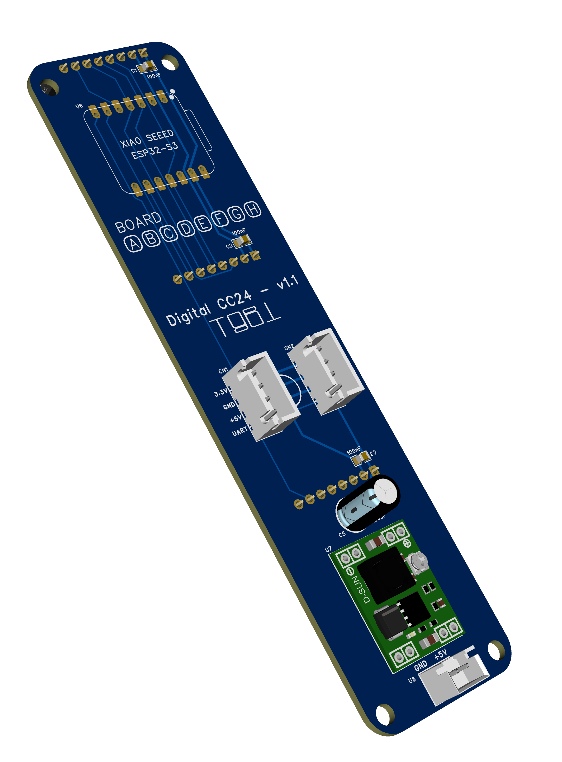
| File | What it is |
|---|---|
3D_PCB3_2026-08-25.png |
3D render (right) |
SCH_Schematic_24_screens_2026-08-25.pdf |
Schematic |
SCH_Schematic_24_screens_1-P1_2026-08-25.png |
The same schematic as an image, for a quick look |
Gerber_PCB3_2026-08-25.zip |
Gerbers + drills, ready to upload |
Netlist_Schematic_24_screens_2026-08-25.tel |
Netlist |


v1.1, 2026-08-25. The pass-through connectors are 4-pin XH carrying
+3.3 V,GND,+5 V,UART— the four wires the prototype was already chaining by hand off a pair of 3-pin headers — and the board lost 8 mm.This revision is otherwise a cleanup: the second bulk cap on the 5 V rail (
C4) is gone, since one is plenty for a board drawing 150 mA, and the outgoing connector is nowCN2rather thanCN3. Nothing on the XIAO moved, so the pin map and every config are unchanged.v1.0 boards still work — they just need the two-run wiring in the assembly photo, because their pass-through is a pair of 3-pin headers rather than one 4-pin.
Superseded files are kept in PCB/old/.
Upload the gerber zip as-is to JLCPCB or any EasyEDA-compatible fab — 2-layer,
1.6 mm, no controlled impedance or other special process. The silkscreen has a
BOARD A B C D E F G H row: tick the board’s letter as you build it, so a
mis-indexed board is identifiable without reading its logs.
What is on it
| Ref | Part | Role |
|---|---|---|
| U6 | Seeed XIAO ESP32-S3 (DIP) | The MCU, on a 2×7 socket |
| U3 / U4 / U5 | 8-pin female headers | Panels A / B / C |
| U7 | MP1584EN module | 5 V → 3.3 V for the panels. Not needed on every board — see How many regulators |
| U8 | JST-XH 2-pin | 5 V power in |
| CN1 / CN2 | JST-XH 4-pin | The whole chain in and out: +3.3 V, GND, +5 V, UART |
| C1–C3 | 100 nF 0805 | Decoupling, one per panel header |
| C6 | 220 µF | Bulk on the 5 V rail |
| C5 | 100 µF | Bulk on the 3.3 V rail |
Power topology
5 V arrives on U8 and goes two places: straight to the XIAO’s VBUS pin
(which runs its own on-board regulator for the MCU), and into the MP1584,
which steps it down to 3.3 V for the three panels. The panels are not run
off the XIAO’s regulator — three GC9A01As would be well past what it can
supply. Because VBUS is on that same +5 V net, plugging USB-C into the XIAO
feeds the board and everything chained to it, and U8 need not be fitted.
CN1 and CN2 carry the same four nets — +3.3 V, GND, +5 V, UART — so
a board loops straight through to the next on a single 4-way cable, panel
supply included. That is why most boards leave U7 empty: see
Power for how many regulators the wall actually needs and where to
feed it.
How the 24 clocks are numbered
Each digit of HH:MM is a 2-wide × 3-tall block of mini-clocks, so the wall is
8 columns × 3 rows. Numbering runs left-to-right then top-to-bottom within a
digit, and the digits go left to right:
           digit 0      digit 1      digit 2      digit 3
          (HH tens)    (HH units)   (MM tens)    (MM units)
            A      B     C      D     E      F     G      H  ← board / wall column
        ┌────────────┬────────────┬────────────┬────────────┐
 row 0  │   0      1 │   6      7 │  12     13 │  18     19 │
 row 1  │   2      3 │   8      9 │  14     15 │  20     21 │
 row 2  │   4      5 │  10     11 │  16     17 │  22     23 │
        └────────────┴────────────┴────────────┴────────────┘
index = digit * 6 + cell cell = row * 2 + col
and back the other way:
digit = index / 6      row = (index % 6) / 2      col = (index % 6) % 2
wall column = digit * 2 + col
Board → column → clocks
One board per column, so a board’s three indices step by 2, not by 1:
| Board | Wall column | Digit | Clocks (rows 0/1/2) | Role |
|---|---|---|---|---|
| A | 0 | hours tens, left | 0 / 2 / 4 | listener |
| B | 1 | hours tens, right | 1 / 3 / 5 | listener |
| C | 2 | hours units, left | 6 / 8 / 10 | listener |
| D | 3 | hours units, right | 7 / 9 / 11 | master — Wi-Fi + SNTP, MP1584, 5 V in |
| E | 4 | minutes tens, left | 12 / 14 / 16 | listener |
| F | 5 | minutes tens, right | 13 / 15 / 17 | listener |
| G | 6 | minutes units, left | 18 / 20 / 22 | listener |
| H | 7 | minutes units, right | 19 / 21 / 23 | listener |
Every panel prints its own position at boot, so a mis-wired module is one log line away:
[C][lvgl_clock]: Partial: clock 18 of 24 (digit 3, row 0, col 0)
Label every panel on the back as you build it — a mis-indexed panel is invisible until its digit happens to change.
Which clocks move, and how often
Worth knowing before you conclude a panel is dead. In mode: demo the fake
clock advances one minute every demo_interval (5 s), so:
| index | digit | changes every |
|---|---|---|
| 18–23 | minutes, units | 5 s |
| 12–17 | minutes, tens | 50 s |
| 6–11 | hours, units | 5 min |
| 0–5 | hours, tens | 50 min |
So the boards worth watching on the bench are G and H (the minutes-units numeral, clocks 18–23): all six move on every demo tick, and any sync error between the two shows up as a single digit visibly forming in two stages.
Board D, the master, is the right half of the hours-units numeral, which only changes every 5 min in demo. For bring-up either borrow a minutes column,
esphome -s clock_index_a 19 -s clock_index_b 21 -s clock_index_c 23 \
        run board_d.yaml
or raise demo_step: (fake minutes per tick, default 1) in common.yaml —
e.g. 137 changes all four digits every tick.
Time sync
The master broadcasts a line on the bus (default every second):
CC24 <epoch> <ms> <mode> <demo_min> <temp> <slot> <movement> <transition_ms> <speed_x100> <hand_rgb> <bg_rgb>\n
<ms> is the part that matters. Nodes only need to agree on which minute it
is, but a node whose clock sits a second off flips its digit a second late, and
on a wall of 24 that reads as a fault rather than as drift. ESPHome’s own
synchronize_epoch_() deliberately ignores corrections under ±1 s and sets
whole seconds only, so the slave platform sets its clock with microsecond
precision instead and flips land within transport jitter. <mode> carries
time / rotate_left / flying_birds / demo so the whole wall animates as
one, and <demo_min> carries the master’s fake-minute counter in demo mode
(-1 otherwise) — without it each board would count its own and the wall would
show 8 different times.
Every field after <mode> is optional on the way in: the parser fills a
default for anything the line does not carry, and ignores anything it does not
recognise. That is what makes a mixed-firmware wall survive — an older listener
reads a newer master’s line and simply stops at the last field it knows. It is
also why the format only ever grows: fields are appended, never reordered
or repurposed, and the mode and movement enums are append-only for the same
reason.
The last five carry how the wall moves and what it is drawn in — the routing rule for a sweep, how
long a sweep takes, and the choreography speed multiplier. They are set on the
master (as Home Assistant entities) and broadcast, because they have to be the
same everywhere: mode_speed scales the time base, so two boards on different
values do not merely look different, they drift apart.
Only the master runs the boot-phase animation
board_d.yaml has the interval: that spins while connecting, flies birds
while waiting for NTP, then shows the time. The slaves deliberately have none:
the mode rides the sync packet, so a slave that also decided for itself would
fight the master once a second.
There is no separate command channel, and there doesn’t need to be — the
mode is field 3 of the packet, and a slave applies it to every widget it
lists. What makes the boot phase work is the <epoch> == 0 case: the master
starts broadcasting the moment it boots, before SNTP has given it a time, and
sends
CC24 0 0 1 -1 # no time yet, mode = rotate_left
A slave reads epoch 0 as “mode only — keep your clock”, so it spins with the master from the first second. Without that the master would broadcast nothing until NTP landed, and the wall would spend its whole boot phase with one column spinning and seven sitting on the boot default with nothing to follow.
It is also what lets demo mode run the whole wall with no network at
all: <demo_min> rides the same mode-only packet, so all eight boards count
the same fake minute straight off the bench supply.
Choreographies, and why they need no coordination
common.yaml sets the wall to break out into an animation from :10 to :45
of every minute:
cycle_modes:
  interval: 1min
  # The 35s window, starting 10s past the minute so it stays clear of the
  # digit flip at :00, is fixed in the component - only the cadence is a knob.
  modes: [birds, wave, spiral, wind]
Each animation is a pure function of the synced clock and the mini-clock’s position in the 8×3 grid, so once two boards agree on the mode and the time they are drawing the same frame of the same figure.
The list is walked in order and wraps, so a repeated entry comes round more
often. Which choreography plays is decided in exactly one place: dc_a on board D,
the first widget listed in that board’s lvgl_clock_id. Everything else — board
D’s other two panels included — is marked a follower, never runs
cycle_modes:, and is handed the mode in the sync packet. Letting all eight
boards pick for themselves would hold only as long as their clocks and their
config agreed to the second; one board a second out at :10 would start a
different animation from the other seven. So cycle_modes: stays in the shared
common.yaml and only the master acts on it.
A board that reboots at :25 is handed the running choreography within a second and joins it mid-figure, rather than starting its own.
wave is the one that proves the wiring: the crest is defined to travel left
to right across all 8 columns, so if board E is showing the phase board D
should be, it is mis-indexed. A column-per-board layout makes that obvious.
The animations also run off the wall clock rather than millis(), which is
what makes any of this work — millis() starts at each board’s own power-on.
That means a slave’s lvgl_clock_id must list all three of its widgets:
lvgl_clock_id: [dc_a, dc_b, dc_c]
The bus is the only thing that moves them, so one left out would sit on the boot default forever.
Debugging the bus
Both roles log it. logger: level: DEBUG gets you a throttled health line
every 10 s from either end; lvgl_clock.sync: VERBOSE adds every packet:
logger:
  level: DEBUG
  logs:
    lvgl_clock.sync: VERBOSE
The three states worth recognising:
| Log line | Means |
|---|---|
TX mode-only (…, no system time yet) |
the master is broadcasting, but has no SNTP — the wall will animate together and show no time |
RX no valid packets yet (0 bytes, …) |
nothing is arriving: wiring, ground, or the master is silent |
RX bad prefix, ignored: '…' / RX overlong line |
bytes are arriving but garbled: baud mismatch or signal integrity |
RX stalled: last packet … ms ago |
the bus was working and stopped: master rebooted, or a wire came off |
The sync dot — reading the wall without a laptop
sync_dot: true puts a dot at 1:30 on each panel that flashes for 120 ms every
second while that board is out of sync. It is a fault light, not a
heartbeat:
| What you see | What it means |
|---|---|
| No dots anywhere | The whole wall is synced. This is the healthy state |
| Every slave blinking, master clean | The master has no usable time yet, or its TX is dead |
| One column blinking | That board’s RX drop, or its ground |
| Dots come back after working | The bus went quiet for 10 s — the board is now free-running and will drift |
The master never shows a dot: it is the time source, so it has nothing to be out of sync with. That falls out of the default rather than being wired up — a widget is “synced” unless a listening time platform tells it otherwise, so a standalone clock never shows one either.
The blinking panels blink together, since the dot is driven off the shared clock. A whole column coming up at once therefore reads as “the master is late”, while one odd panel in a column reads as “that node’s wiring”.
Only the master has a network
wifi:, api: and ota: live in board_d.yaml alone. The other seven take the
time off the UART and have no network stack at all, which means:
- One set of credentials on the wall, and one board that cares whether the Wi-Fi is up. Seven boards that cannot fail to associate, cannot wait on DHCP, and boot to a spinning clock in a second.
- No OTA on the listeners. They are flashed over USB. With eight boards rather than 24 that is a much easier trade than it used to be, but it is the real cost — decide before the frame is glued shut.
- Their heap sensors still report to the USB console via
logger:; they just have nowhere to publish.
If you would rather have OTA on all eight, add wifi: and ota: (and skip
api:) to common_base_esp32_s3_xiao.yaml instead — nothing else changes,
because the time still comes off the bus either way.
Power
A board draws about 150 mA at 5 V — one XIAO ESP32-S3 plus its three panels with backlights on. That scales linearly, because every board is identical:
| Current at 5 V | Power | |
|---|---|---|
| One board (3 panels) | ~150 mA | ~0.75 W |
| Full wall, 8 boards | ~1.2 A | ~6 W |
| Supply | 2 A USB | ~40% headroom |
So a 2 A USB supply carries the whole wall with room to spare.
Worth knowing before wiring it:
- Size for inrush, not the average. All eight boards come up together, and 24 backlights striking at once plus the master associating to Wi-Fi pulls well above the steady 1.2 A for a few hundred milliseconds. 2 A covers it; a 1 A supply would brown out at switch-on and present as “a random board won’t boot”, which is a power fault wearing a firmware costume.
- The master draws more than the slaves. It is the only board running a Wi-Fi stack, worth roughly 50–80 mA extra in bursts. If anything is marginal, it fails there first.
- There is no low-power state.
BLKis tied to +3.3 V on the PCB, so the panels are always at full brightness. Dimming would be the obvious way to cut the wall’s draw, since the panels are most of it, but it needs a board revision that routes D7 toBLK.
How many regulators, and where
One MP1584 for the whole wall is enough, and the 3.3 V rail daisy-chains with
the 5 V. The remaining seven boards leave U7 empty. This is measured, not
estimated: across four chained boards the drop is 0.01 V on both rails. The
one module then carries the whole wall’s 3.3 V load, which an MP1584 — a 3 A
part — takes without heatsinking.
Two consequences worth designing around:
- Feed the chain in the middle — board D or C — so no run is longer than four boards in either direction, the length already measured. It costs nothing but where you put the connector.
- A second module is optional, and if you fit one, give each its own rail.
Populate
U7on D and C, then omit the+3.3 Vwire from the single cable between them. Paralleled trimmer-set buck modules do not share a load — the one set a few millivolts higher simply takes all of it — so tying the two outputs together makes a two-regulator wall behave worse than a one-regulator wall, not better.GND,+5 VandUARTstill pass through that cable, so the chain and the sync bus are unbroken.
Memory
The S3’s 8 MB of octal PSRAM is what makes three panels per board unremarkable.
direct_draw: true also skips the widget’s own canvas and renders straight
into LVGL’s buffer — a 240×240 RGB565 canvas is 115 KB, so three of them would
have been 345 KB that the build simply never allocates.
The base package enables the memory debug sensors (free, block). Watch
block: a draw buffer needs one contiguous chunk, so it can fail while free
still looks fine. If a widget runs out it logs an error and disables itself — a
blank panel rather than a crash.
Frame rate
Each 240×240 panel needs ~11.5 ms for a full frame at 80 MHz, and all three
share one SPI bus, so ~34 ms is the floor for a full sweep. render_interval:
33ms (≈30 fps) matches that; asking for 60 just starves the next frame.
How the configs fit together
Eight boards, two roles, and one copy of every setting. The build is layered so that a board file contains only what makes that board different — which is three clock indices, and on the master its network:
board_d.yaml  ── THE MASTER ───────────────────────────────────┐
  wifi: / ota: / uart: TX / sntp / broadcaster / temp sensor   │
  └─ common.yaml                                               │
                                                               │
board_a.yaml  ── A LISTENER (and b, c, e, f, g, h) ────────────┤
  three clock indices, nothing else                            │
  └─ common_slave.yaml                                         │
       uart: RX / lvgl_clock time platform / hostname          │
       └─ common.yaml                                          │
                                                               │
                     common.yaml  ◄────────────────────────────┘
                       spi: (one bus) · display: ×3
                       ├─ common_base_esp32_s3_xiao.yaml
                       │    esp32 · psram · logger · pin names · colours
                       ├─ panel.yaml   vars: lvgl_a, dc_a, ${clock_index_a}
                       ├─ panel.yaml   vars: lvgl_b, dc_b, ${clock_index_b}
                       └─ panel.yaml   vars: lvgl_c, dc_c, ${clock_index_c}
                            one LVGL instance + one lvgl_clock widget
| File | What it is |
|---|---|
common_base_esp32_s3_xiao.yaml |
Board, PSRAM, logger, the pin substitutions, colours, heap sensors. No network — that lives in board_d.yaml |
panel.yaml |
One panel: its LVGL instance and its single mini-clock, with every widget setting. Included three times |
common.yaml |
The SPI bus, the three display: entries, and the three panel.yaml includes |
common_slave.yaml |
The listener half: UART RX, the lvgl_clock time platform, and the hostname |
board_d.yaml |
The master. Wi-Fi, SNTP, UART TX, the boot-phase animation, the temperature sensor, clocks 7/9/11 |
the other seven board_*.yaml |
The listeners. Each is four lines: an include and its three clock indices |
secrets.yaml.example |
Copy to secrets.yaml (gitignored). Only board_d.yaml reads it |
Two different include mechanisms, and why both are needed
packages: merges a file in wholesale. That is how the role files pull in
common.yaml and how common.yaml pulls in the base — each layer adds keys,
and a later substitutions: block overrides an earlier one. It is composition,
and it happens once per file.
!include with vars: parameterises a file, so it can be included more than
once. panel.yaml is a complete panel — LVGL instance, widget, choreography
settings, render_interval, cycle_modes, the lot — and common.yaml pulls
it in three times, changing only four things each time:
panel_a: !include
  file: panel.yaml
  vars:
    lvgl_id: lvgl_a
    display_id: my_display_a
    widget_id: dc_a
    clock_index: ${clock_index_a}
This is the distinction that makes the layering work: substitutions: are
global to the build, vars: are local to one include. There is exactly one
clock_index in a substitution namespace, so three panels could never each
have their own — but three includes can each carry their own vars:. The
result is that ~60 lines of widget configuration exist once, not three times,
and adding a fourth panel would be four lines in common.yaml rather than
another copy of the widget.
What overrides what
| Substitution | Default | Overridden by |
|---|---|---|
clk_pin, cs_pin_a… |
common_base_esp32_s3_xiao.yaml |
the command line, if your wiring differs |
clock_index_a/b/c |
common.yaml (0 / 2 / 4) |
every board_*.yaml — this is all a listener file contains |
clock_mode |
board_d.yaml (time) |
-s clock_mode demo, master only |
Because substitutions resolve at codegen, -s works on any of them without
editing a file:
esphome -s clock_index_a 19 -s clock_index_b 21 -s clock_index_c 23 \
        run board_d.yaml
So a listener board file really is just its column:
packages:
  slave: !include common_slave.yaml

substitutions:
  clock_index_a: "1"
  clock_index_b: "3"
  clock_index_c: "5"
The hostname is derived from the first index inside common_slave.yaml
(cc24-clock-${clock_index_a}), so even that does not have to be repeated.
One YAML trap worth knowing. A substitution inside a flow sequence fails to parse —
displays: [${display_id}]makes the parser read${as the start of a flow mapping. Write it in block form instead:displays: - ${display_id}