Assembly, wiring and flashing
Building the 24-round-screen wall, in the order the steps actually happen. What you need — the BOM, the frame, the boards — is on the build’s front page; how it works underneath is in Technical details.
Hardware assembly
Build and prove one board before you build eight. A single XIAO tests every carrier: solder a board, plug the XIAO into it, confirm all three screens come up, then move that XIAO to the next board. Eight boards assembled and only then powered is eight boards to debug at once.
Build board D first — it is your test rig. D is the master and the
regulator board: it is the only one with wifi:, and it carries the U7
MP1584 and the 5 V input. That is deliberate — the middle of the row, so the 3.3 V it makes has at most four boards to reach in either
direction. That module is the only source of the 3.3 V the panels run on: a
board without one has no panel supply of its own, so testing it means chaining
it to the regulator board with a 4-pin cable and letting +3.3 V come down the
chain. Keep that board on the bench for the rest of the build.
1. Solder one board, lowest parts first.
| Order | Parts | Note |
|---|---|---|
| 1 | C1–C3, 100 nF 0805 |
Only if you are fitting them — see the BOM. SMD, so they go on while the board is still flat |
| 2 | U7, the MP1584 module |
Only the one or two boards that carry a regulator. It lies flat on its footprint and is soldered through its pads — poor-man’s SMD, and much easier before the tall parts |
| 3 | U3/U4/U5, U6 |
The three 8-pin panel headers and the 2 × 7 XIAO socket |
| 4 | CN1, CN2, U8 |
The 4-pin chain connectors, plus the 2-pin power input if you are using one |
| 5 | C5, C6 |
The electrolytics: tallest, so last. Watch polarity |
2. Set the MP1584 to 3.3 V — before any panel is plugged in. These modules ship adjustable and usually well above 3.3 V. Power the board with the panel headers empty, turn the trimmer until pin 2 of a panel header reads 3.3 V, then fit the panels. Getting this wrong once costs three displays.
3. Flash one XIAO as the master and test three screens. Do this on the
board you fitted the MP1584 to: board_d.yaml is the only config that brings
up Wi-Fi and SNTP, so that one board needs nothing else — no bus, no second
board:
esphome run board_d.yaml
All three panels should light, the right way up, sweep to 12 together during
the 10 s startup_align, then show the time and break into a choreography at
:10. Nothing special is needed to see movement — the stock config cycles
birds, wave, spiral, wind, love and temp on its own, so a board that
is working is obvious from across the room. If one panel stays dark it is that
panel’s chip select or its header joints; the other two prove the shared SPI,
DC and reset lines are fine.
4. Build the remaining seven boards, testing each as you go by moving that
same XIAO across. Tick the board’s letter in the silkscreen
BOARD A B C D E F G H row as you finish it.
These boards have no regulator, so they cannot power their own panels. Hook the board under test to the MP1584 board with a 4-pin chain cable before you plug the XIAO in —
+3.3 Vis one of the four nets, so the regulator board feeds the panels across the link exactly as it will in the finished wall. Three dark screens on an unchained board is the expected result, not a fault.
5. Flash a second XIAO as a listener and test the bus. With board_b.yaml
on it, join it to C with one 4-pin chain cable — which also gives it the 3.3 V
its panels need:
esphome run board_b.yaml
The sync dots are the test. A listener draws a dot on each face until it
has heard a valid packet, and within a second of the master coming up all three
should go dark. If they stay, the bus is not working — see
Debugging the bus. The listener also picks up the
master’s choreography, so the two boards animating in step is the second half
of the proof. Walk that listener XIAO down the chain and repeat for every
board, so each carrier’s CN1/CN2 is proven before anything goes into the
frame.
6. Wire the chain. One 4-pin cable per hop, seven in total, fed in the middle. The diagram and the per-hop detail are in Wiring below.
7. Run the whole wall on the bench, before anything goes into the frame.
Flash all eight (board_d.yaml over the network, the rest over USB), chain
them, and power the middle. Everything up to here has been tested
two boards at a time; this is the first time the wall is a wall, and it is far
easier to fix flat on a table than screwed to a frame.
What to look for, in order:
- All 24 sweep to 12 together during the 10 s
startup_align, then land on the time together. A column that lags or never arrives is a bus problem at that board’sCN1. - Every sync dot is dark. One board still dotted means it is not hearing
the master — that hop’s cable, or its
CN1/CN2joints. - The time reads correctly. A board plugged into the wrong column shows a
scrambled digit, and that is a
clock_index_*mistake in its YAML, not a wiring one. - Wait for
:10and watch a choreography cross the wall.waveandwindtravel left to right across all eight columns, so they are the only test that proves the column ordering and the shared animation clock end to end. If the wave arrives at a column out of turn, that board has the wrong indices.
8. Prove every panel works before any of it is glued. Hot glue is not meant to come back out, so a panel that turns out to be dead after mounting is a real problem. Walk a carrier along and light all 24 first — three at a time, watching for a panel that stays dark, comes up the wrong way round, or shows tearing. Steps 3 to 7 already do most of this; the point here is that no panel goes into the case until you have seen it draw a clock.
9. Fit the panels into the printed case — and check the orientation. The case is one printed part with 24 round cutouts; the panels sit behind it so only the round glass shows through. Every panel goes in the same way round, with its driver IC at the top:
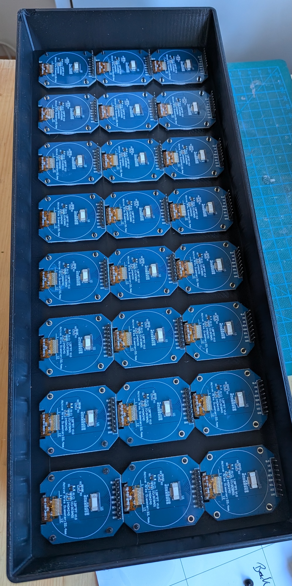
Eight rows of three, one row per carrier board. Orientation is the mistake to
watch for: a round panel mounted a quarter-turn out puts that clock’s 12 where
its 3 should be, and nothing in the config can correct it per panel — the whole
board shares one rotation:. It is also invisible until the hands move,
because a round display looks identical whichever way up it is.
10. Glue them in. Hot glue is enough — a bead at two or three points on each panel’s edge, not over the header:
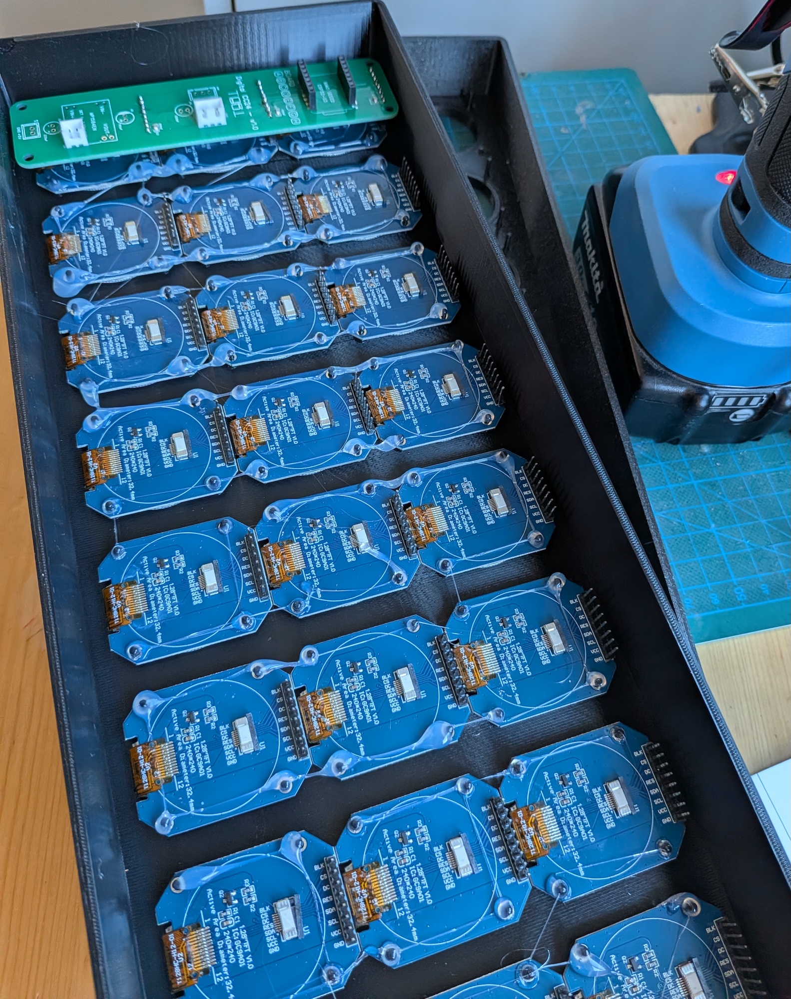
Each panel’s 8-pin header points inwards so a carrier lands straight onto its three. Lay one bare carrier on before gluing the rest of a row, to check the fit.
11. Push the finished carriers onto the panels and wire the chain. Each carrier presses onto the three headers of its row; then one cable per hop, all the way along, as in Wiring:
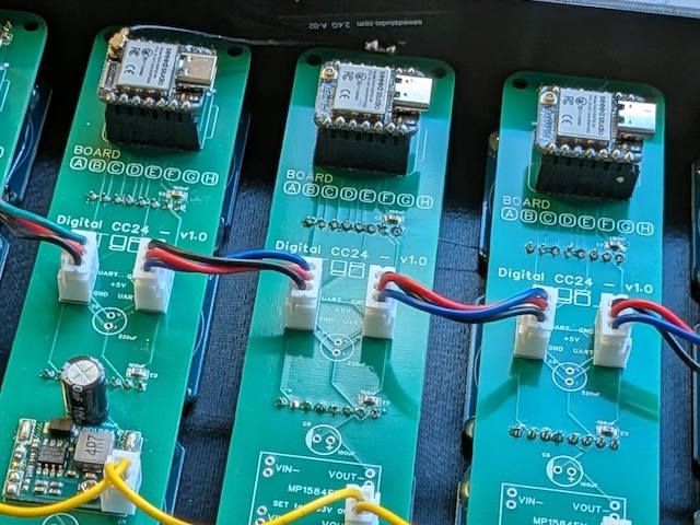
↑ All eight carriers seated and chained, before the face plate goes on. One MP1584EN is fitted, on the middle board — the other seven footprints are empty, which is the whole point of feeding the middle. The scale underneath reads 730 g, the finished weight.
Note this is PCB v1.0. Its pass-through is a pair of 3-pin headers, so
the chain is two runs — the red/blue pairs carrying GND, +5 V and UART,
and the separate yellow lead carrying +3.3 V the length of the wall. v1.1,
the revision in PCB/, replaces both with a single 4-pin XH per
hop, so a finished board of that revision has one cable in and one out and
nothing else.
What the photo does show, and still holds on v1.1: only one MP1584EN is
fitted for the whole wall — the other seven footprints are empty, exactly as
How many regulators describes.
Powering over USB-C rather than
U8? Use a right-angle USB-C cable. A straight plug does not clear the frame.
Wiring
One 4-way cable per hop, and that is the entire harness. CN1 and CN2 carry
the same four nets, so each board loops straight through to the next — power
and the sync bus in one run:
   4-pin XH chain cable:  +3.3 V . GND . +5 V . UART     7 cables, 8 boards

                 5 V IN — XH-2 on U8, or a
               90-degree USB-C into D's XIAO
                             |
                             v
  +-----+ +-----+ +-----+ +-----+ +-----+ +-----+ +-----+ +-----+
  |  A  | |  B  | |  C  | |  D  | |  E  | |  F  | |  G  | |  H  |
  +----o+-+o---o+-+o---o+-+o---o+-+o---o+-+o---o+-+o---o+-+o----+
   col 0   col 1   col 2   col 3   col 4   col 5   col 6   col 7

   D = master (Wi-Fi), the MP1584, and 5 V in   o = CN1 / CN2, 4-pin XH
   C = a 2nd MP1584, only if you fit one        end boards use only one
- One cable per hop, seven in total. The two end boards leave one connector unpopulated. One board is one wall column, left to right, and its three panels are that column top to bottom.
- Feed the middle, not an end — board D or C. That keeps every run to four boards or fewer, which is the length actually measured (0.01 V of drop).
- Power enters either through
U8or over USB-C. The XIAO’sVBUSpin sits on the same+5 Vnet, so plugging one USB supply into the middle board’s XIAO runs the whole wall andU8need not be fitted at all. - Board D is the master, and the natural place for the MP1584 and the 5 V
feed as well — one board in the middle carrying the regulator, the power
input and the network. It drives
partial: 7 / 9 / 11, its own column, like every other board. - Fitting a second MP1584? Split the 3.3 V rail. Populate
U7on D and C, then leave the+3.3 Vwire out of the one cable joining them, so each module feeds its own half of the wall.GND,+5 VandUARTstill pass through. Never tie the two outputs together — why.
The pin map itself — which XIAO pin does what, and why the bus cannot sit on D6 — is in Per-board pin budget under Technical details.
The sync bus rides the same cable. UART is the fourth wire, so it chains
along with power instead of needing its own run, and the master’s TX reaches
every board through the daisy chain — in both directions, since the master sits
in the middle. It is still one TX driving high-impedance RX inputs: master to
slaves only, so a slave sends nothing back. Same silkscreen pin, D1, on
every board, with the role deciding direction. At 115200 baud on a bench that
is comfortable; across a frame with metres of cable, use RS-485 transceivers.
Flash the firmware
esphome run board_d.yaml      # master, over the network once it is on Wi-Fi
esphome run board_a.yaml      # …and the other seven, over USB
flash-all.sh does the whole wall and pauses between boards
so you can move the USB lead. macOS and Linux:
./flash-all.sh                    # all eight, over USB, in order
./flash-all.sh -b a,b,c           # some of them
./flash-all.sh -b a,b,c,e,f,g,h,d # listeners first, master last
./flash-all.sh -p /dev/cu.usbmodem1101   # skip the port prompt
./flash-all.sh --build-only       # check a change compiles for all eight
./flash-all.sh -m cc24-board-d.local     # master over the network, not USB
Before each board it draws the wall as you are looking at it — from behind, where the USB sockets are, so board A is on the right — with that board’s column picked out:
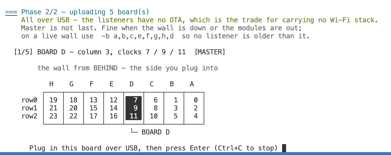
Columns are zero-based. Board D above is column 3 and the fourth one along — so “column 4” counted the natural way lands on D when it means E. That mismatch is the whole reason the picture is there: the highlighted block is unambiguous in a way the number is not.
It also compiles all eight before uploading anything. A compile error found halfway through leaves you with a wall running two firmwares and a board in your hand.
When the flashing order matters
It does not, if the wall is powered down or the modules are out of their
carriers — which is the normal case, and why the default order is simply
a,b,c,d,e,f,g,h.
It does if you are updating a wall that stays running while you work through it. The mode is an integer on the sync bus and new modes are appended, so a newer master can broadcast a mode an older listener does not know — and that listener silently ignores the mode field and holds its last animation. The other way round is harmless: an older master only ever sends modes a newer listener already understands. So for a live wall, put the master last:
./flash-all.sh -b a,b,c,e,f,g,h,d
The script says so itself when the master is not last.
Only board D has ota:, so by default everything goes over USB. Give it
-m cc24-board-d.local and the master goes over the network instead — useful
once the wall is mounted and D is the only board you can still reach.
Each board gets its own hostname and build directory, so the eight builds don’t collide.
clock_mode is a master-only knob — it lives in board_d.yaml, because
the master owns the wall’s mode and the other seven follow whatever it
broadcasts. There is nothing to set on a slave, and nothing to keep in step by
hand. The default is time, which is all you need: the stock config already
animates on its own, cycling the choreographies once a minute at :10.
demo is there only if you want a fake minute every 5 s — useful when you are
watching the hours-tens column, which otherwise changes twice a day. Pass it
rather than editing the file, and set it on the master alone; the rest of the
wall adopts it off the bus, minute counter included:
esphome -s clock_mode demo run board_d.yaml