Levoit LV-PUR 131S - Custom Firmware (ESPHome)
This model is discontinued and known for reliability issues (sudden shutdown syndrome). This project upgrades the original hardware with modern components while maintaining form factor compatibility.
Hardware Upgrades:
- MCU: Original ESP12F → Xiao Seeed ESP32-C3
- Sensor: Original PM1003 → PM5003 (significantly improved air quality detection)
The original PM1003 sensor was unreliable; spare PM5003 components were substituted for better performance. Legacy PM1003 code is preserved as commented reference.
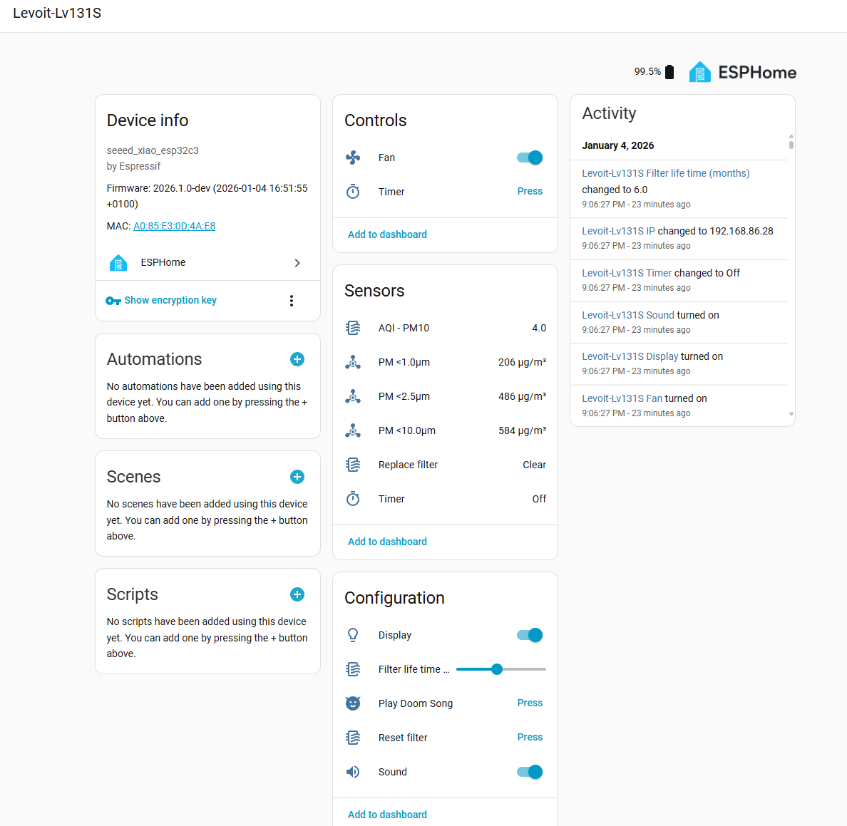
Features
- Home Assistant Integration (no cloud required)
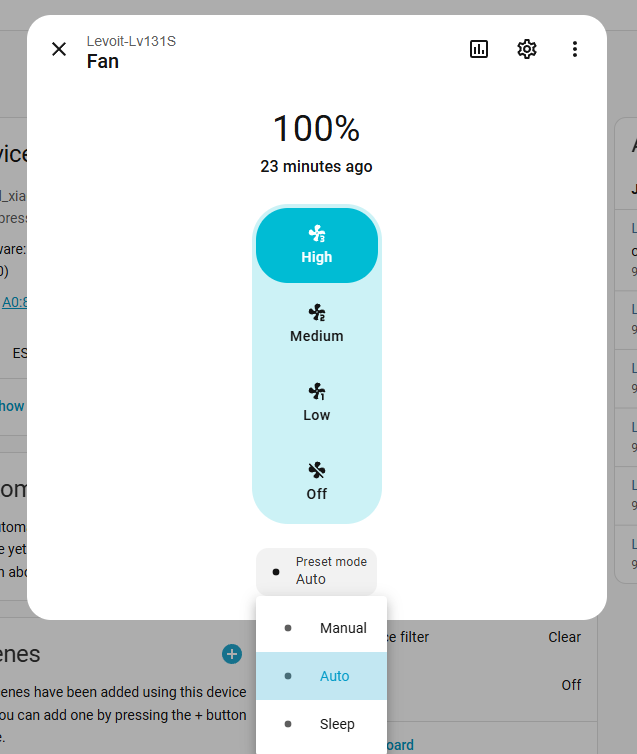
- Full fan support with 3 manual speeds + Auto/Sleep modes
- Filter lifetime tracking based on actual runtime and usage
- Display on/off control and brightness
- Reset filter button (hold 5s until beep, or trigger via HA)
- Timer support (30 minutes to 12 hours)
- Unique Features
- Hidden Doom! easter egg (hold Sleep button 4 seconds)
- Configurable sound feedback (buttons only, not remote control)
- Improved PM2.5 sensor (PM5003 vs original PM1003)
Reliability Issues - “Sudden Death” Syndrome
This model experienced manufacturing defects leading to premature failures. Resources:
- Reddit Discussion - Manufacturing Defect
- YouTube - Diagnosis and Repair
- YouTube - Component-Level Analysis
Root Cause: Overvoltage transients reaching the MCU/PCB, typically burning the voltage regulation diode and main microcontroller.
Experience: The original ESP12F in this device was destroyed; diode damage was also observed. A replacement unit obtained under warranty enabled reverse engineering and development of this custom ESPHome firmware.
Hardware Upgrade Project (“The Hack”)
Required Parts
- Broken or working Levoit LV-PUR131S
- Xiao seeed esp32-c3
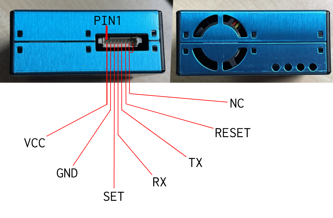
- PM5003 particle sensor
- Wires and some connectors
Required Tools
- Soldering Iron
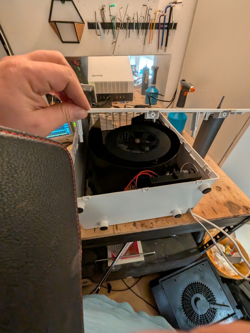
De-Assembly
- Remove all screws on the outside (white plastic), 3 on bottom, 2 top (left and right, long screwdriver!).
- Remove the Filter
- Remove all screws, one is a triangle shaped one!
- Open the front carfully from the bottom
My power supplies are still working, if needed get a 24V DV like a Meanwell LRS 50-24 + aa 24V to 5V bucket converter.
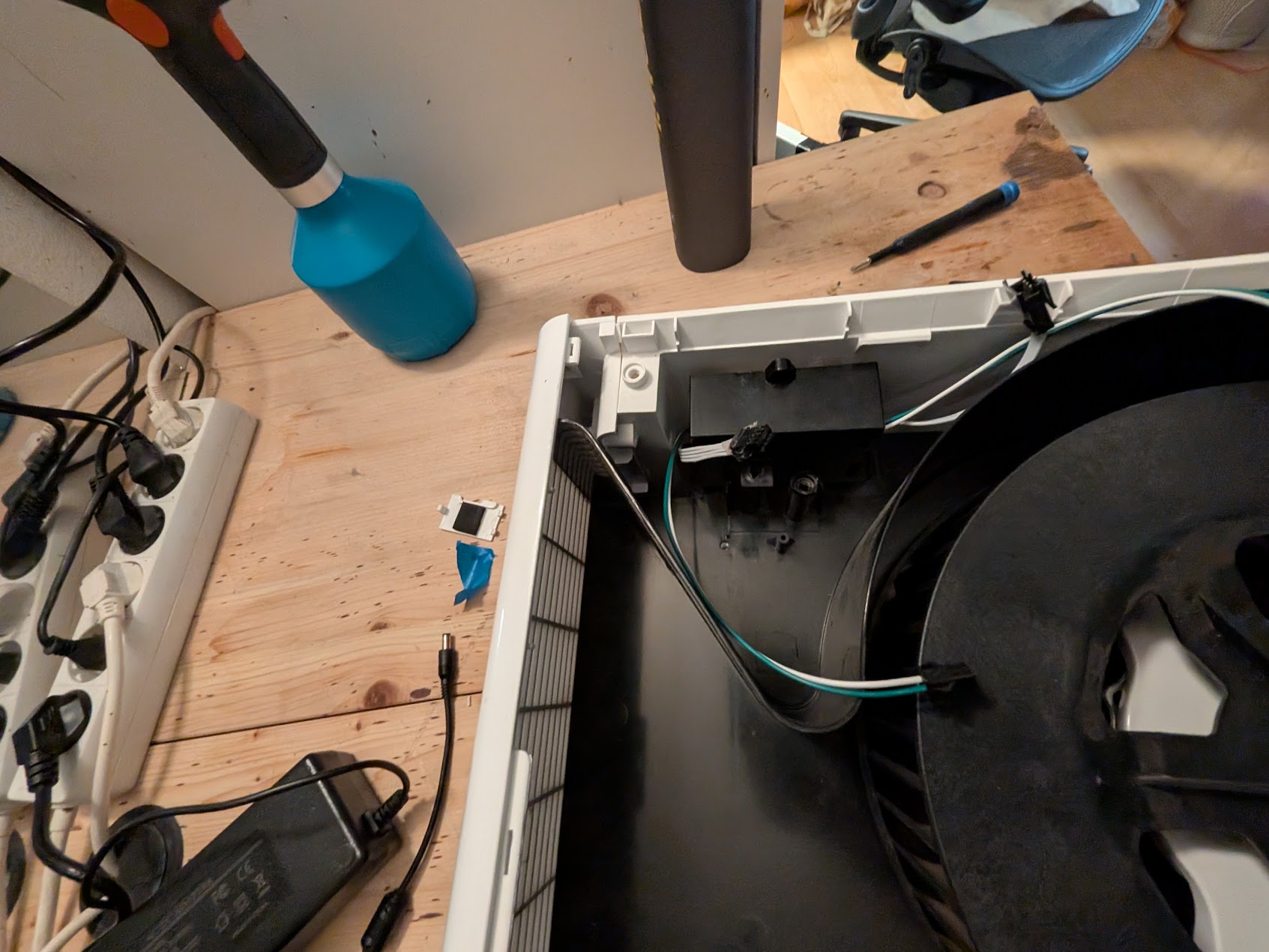
- Unplug the Switch for checking if the back is open
- Unplug the connection to the MCU
- Unscrew all screws holding the Fan base in
- Remove the Fan base from the bottom
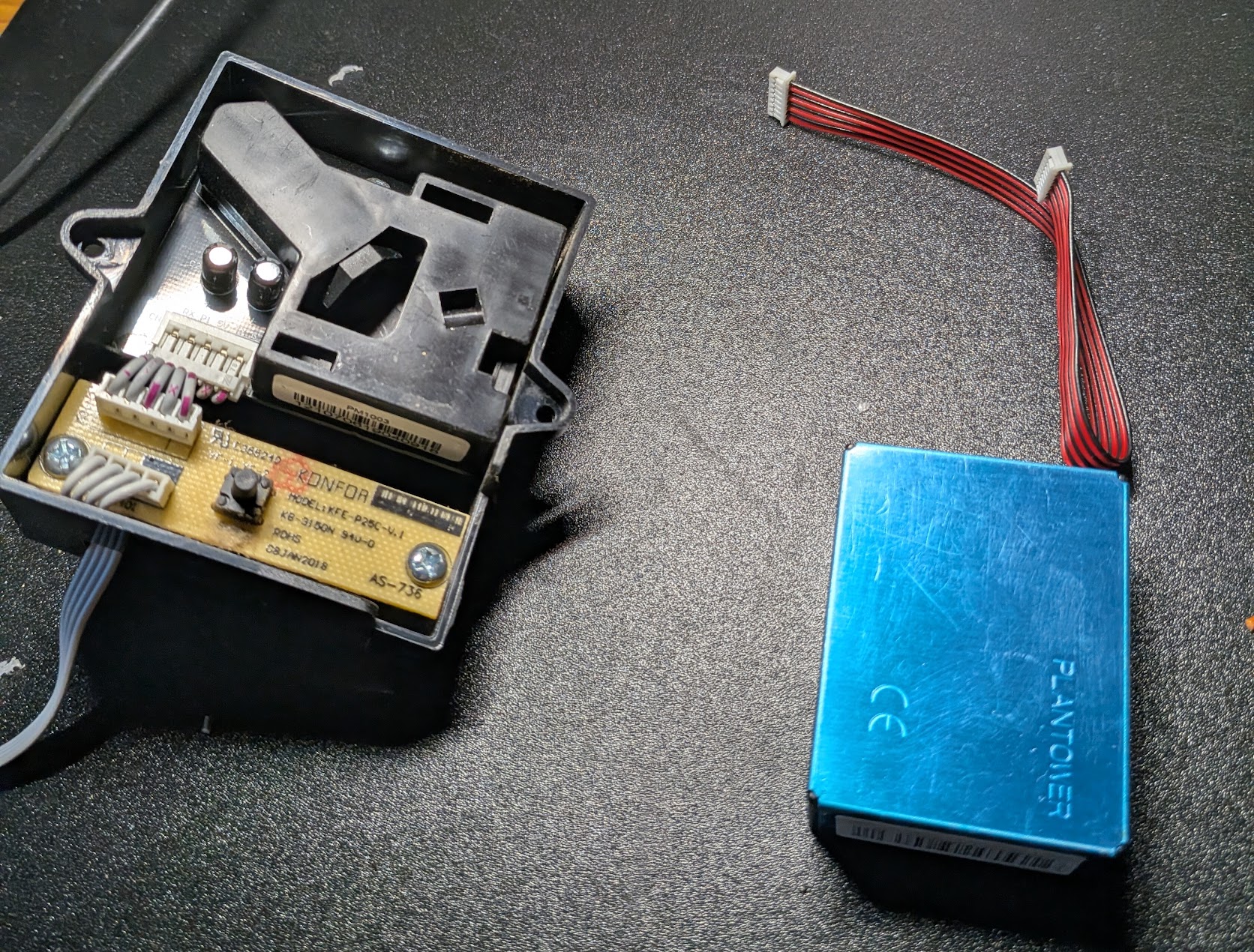
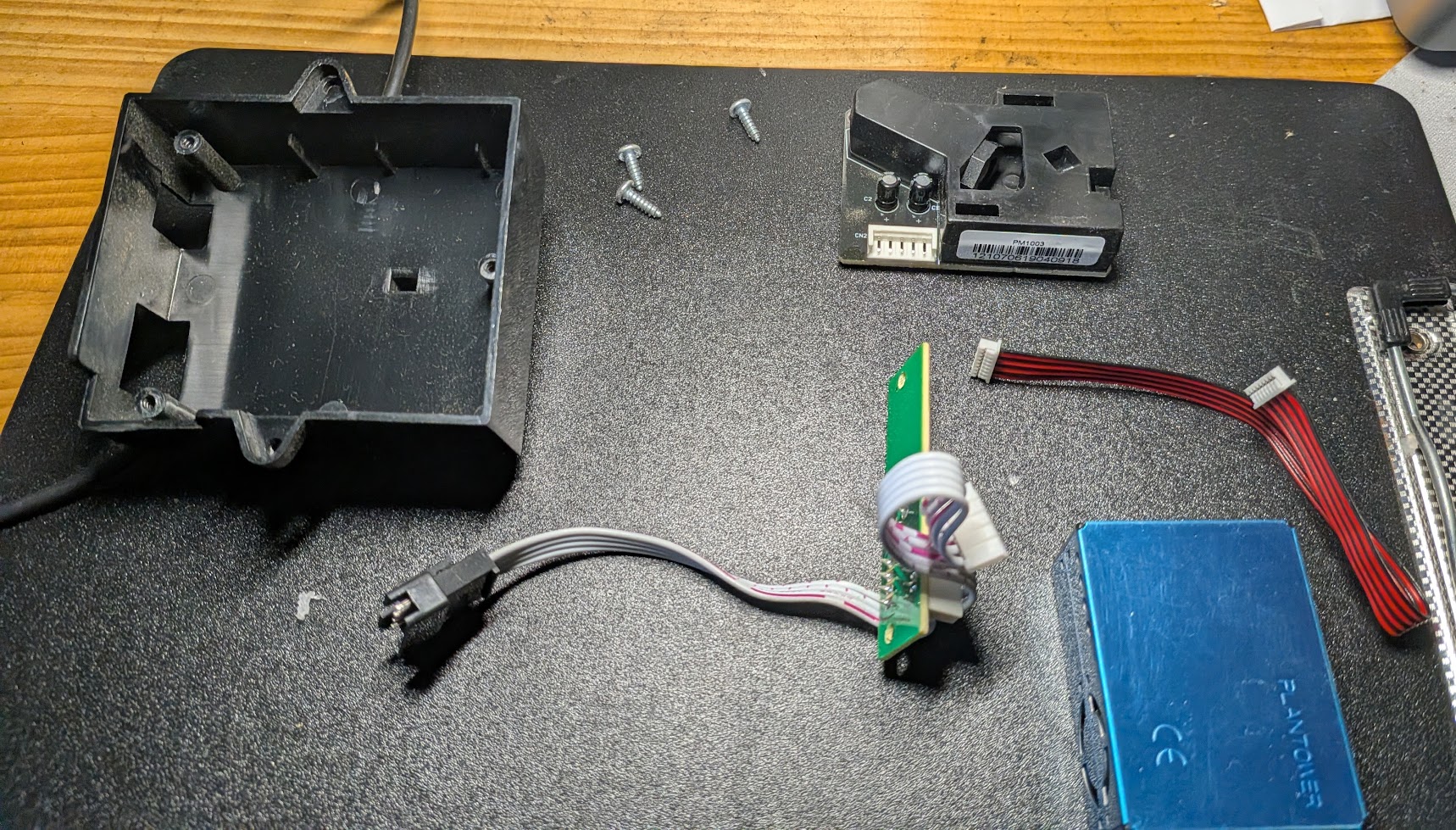
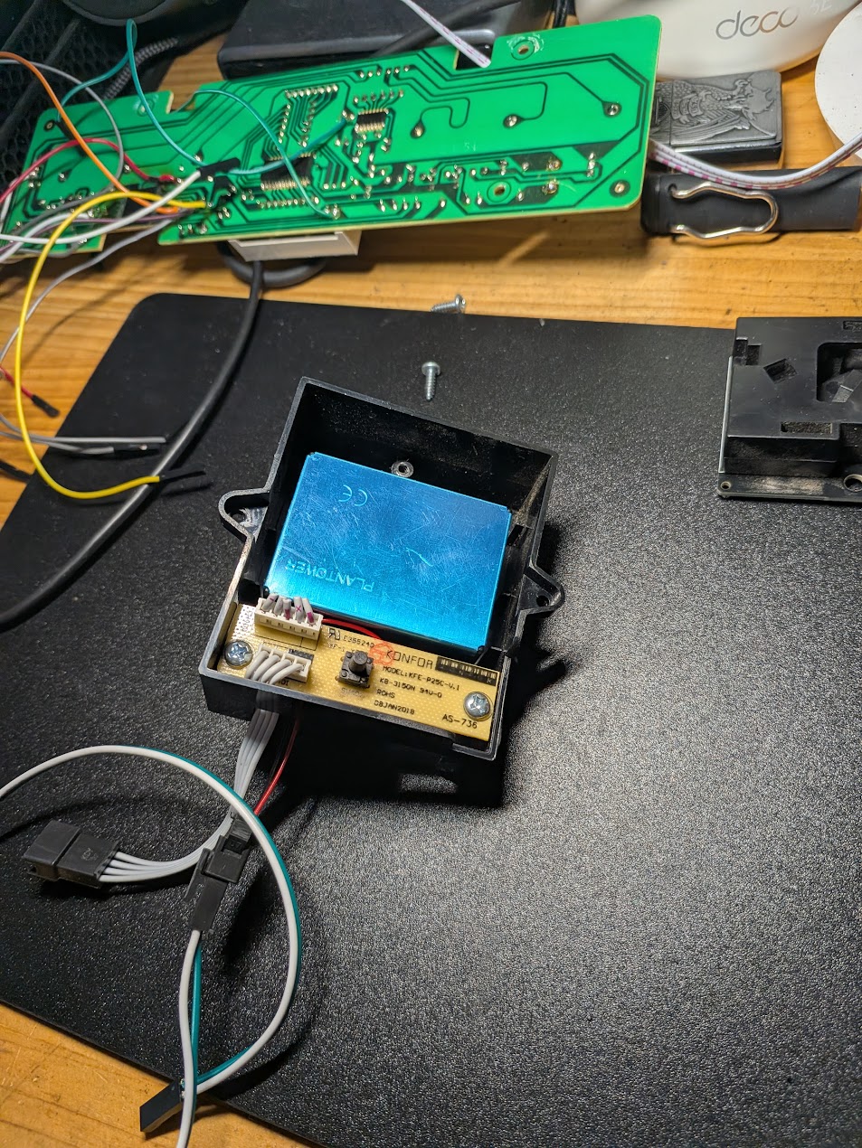
- Unplug the Sensor and unscrew it
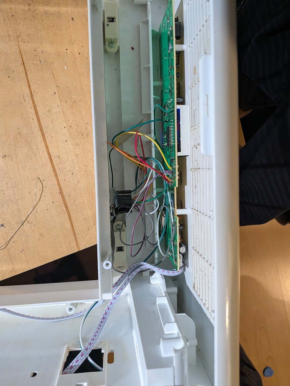
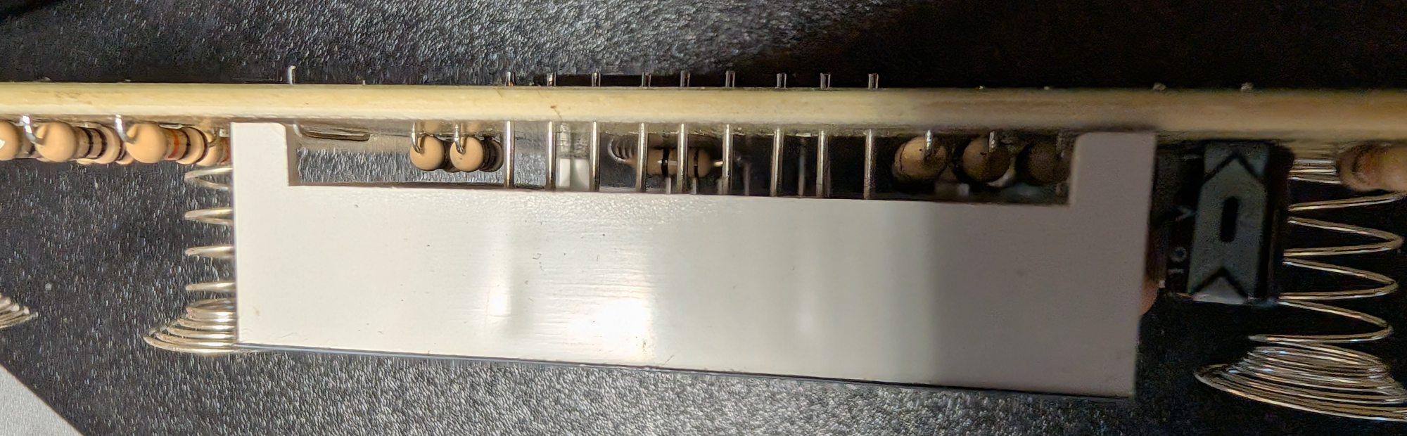
- To remove the PCB (Optional!?)
- First screw can easily be unscrewed
- i used pliers for the other 2 ones, as i would need to remove the top panel and i did not find a way todo this undestrutive.
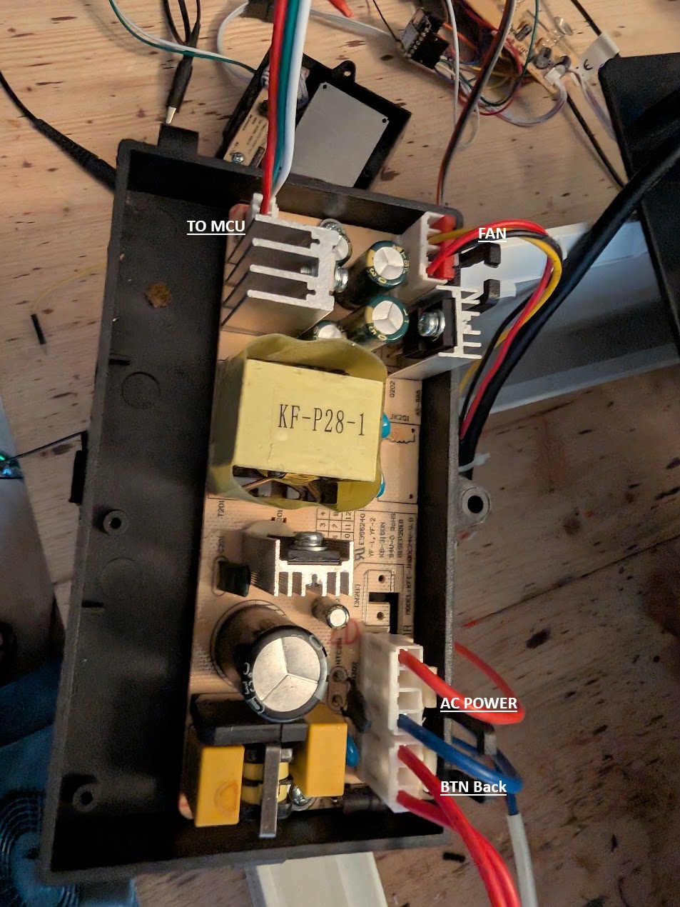
Hack / Modify PCB
Might be possible without removing the PCB! i did not try but it seems there is enough room!
Soldering is a bit hard/wired, some protective film seems to be applied.
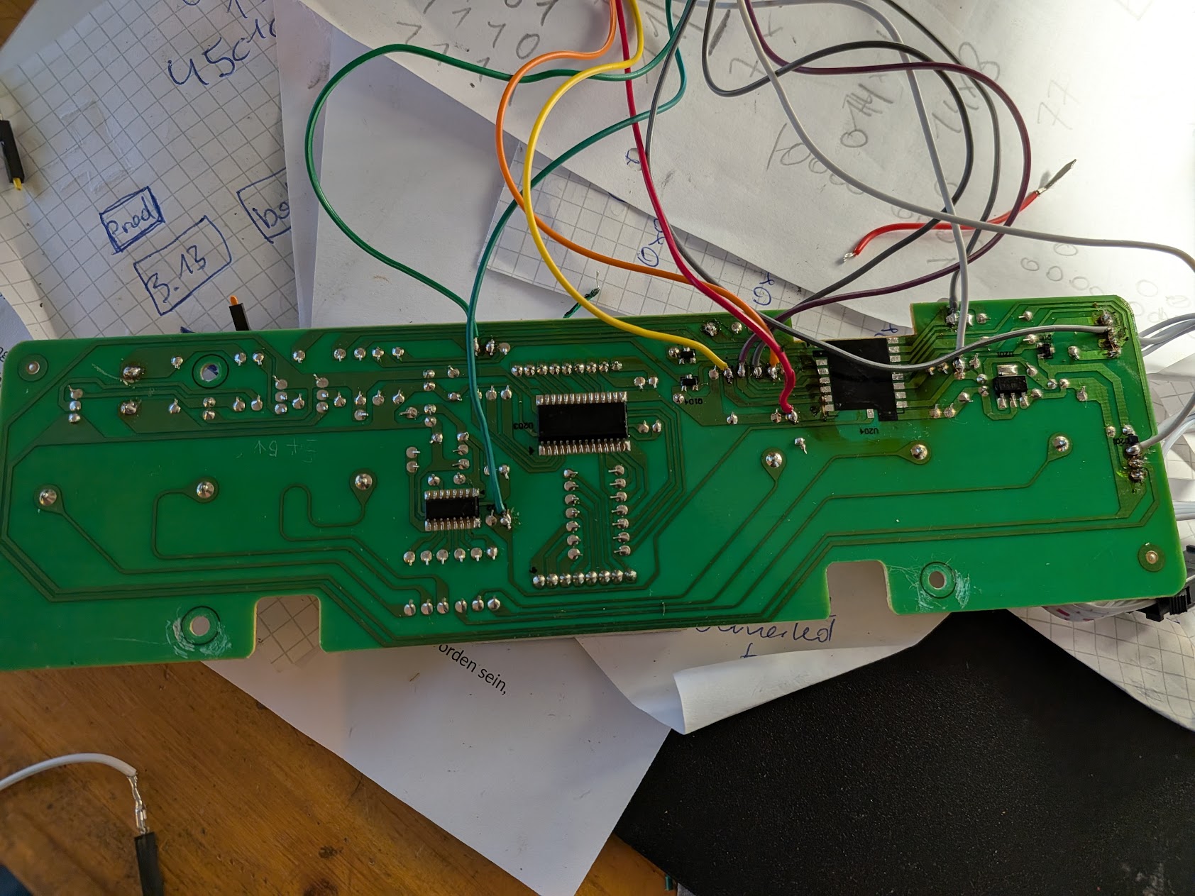
- Remove the old MCU or cut power and gnd at least
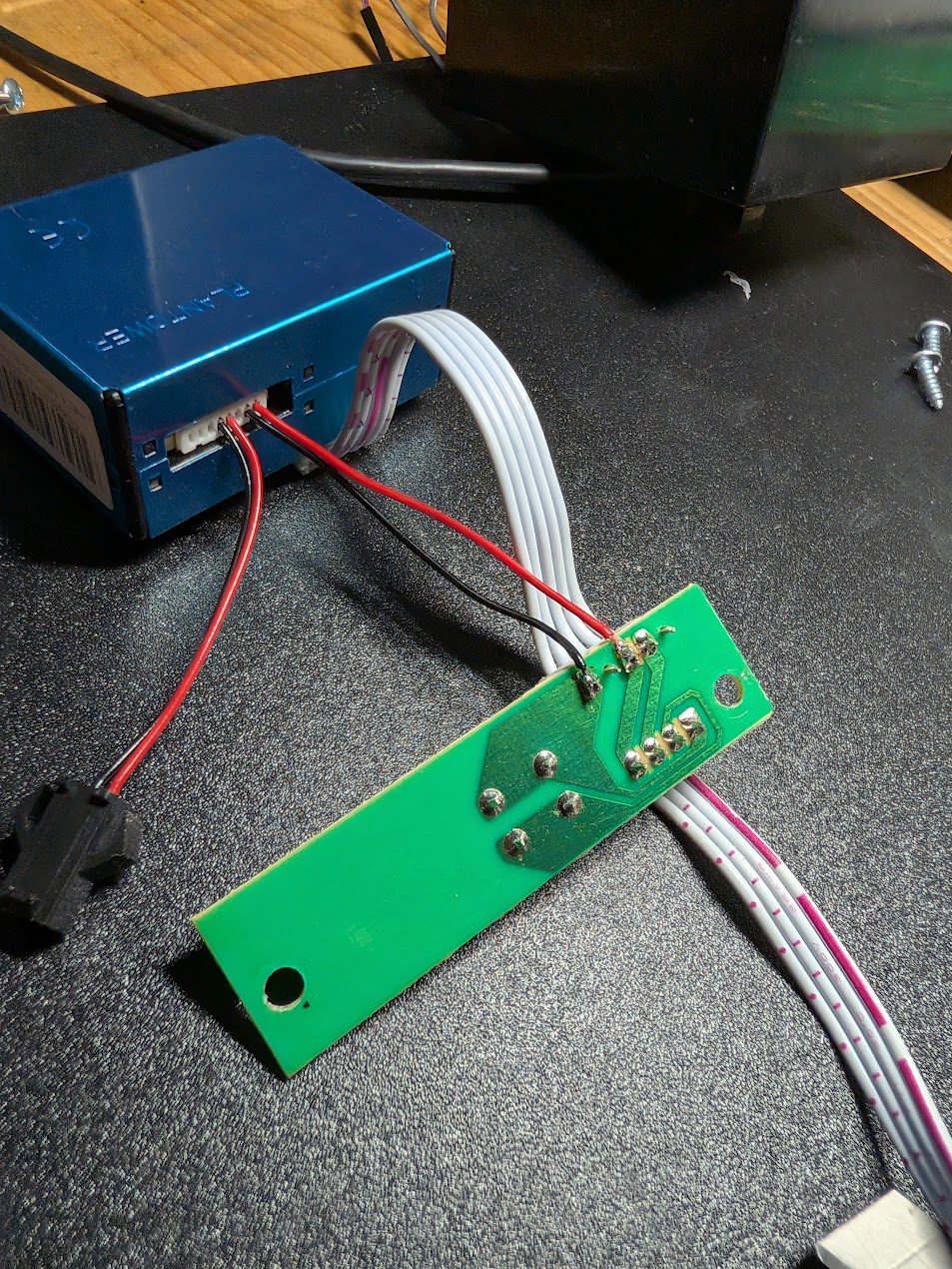
- Unplug the old sensor from the case
- I used Power and GND from the old sensor and added 2 wires for the UART of the PM 5003, this allows to still use the reset BTN!
-
Solder the wires for the new MCU
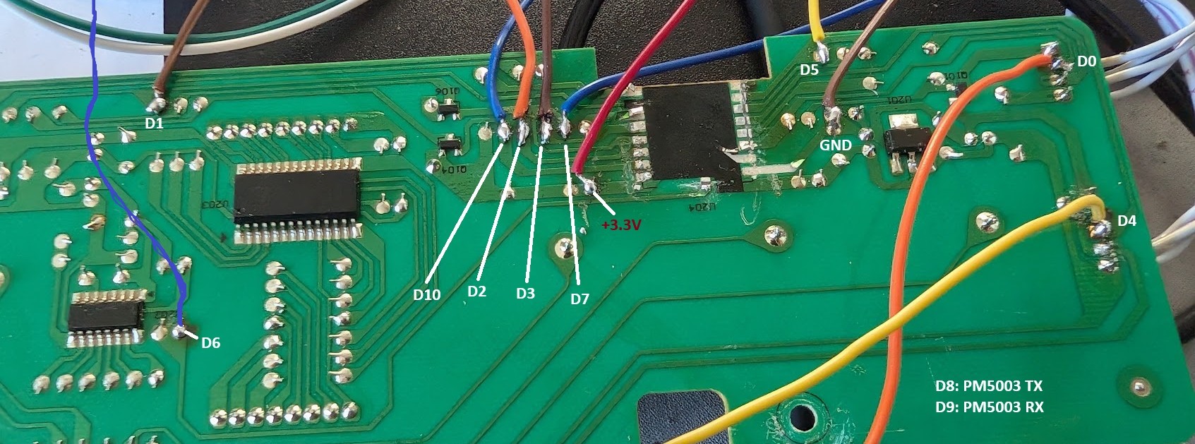 Note: D5 resistor is not required if PM5003 sensor is used.
 - Flash Firmware: configure
secrets.yamlwith WiFi and Home Assistant encryption key- Requires ESPHome 2026.01+
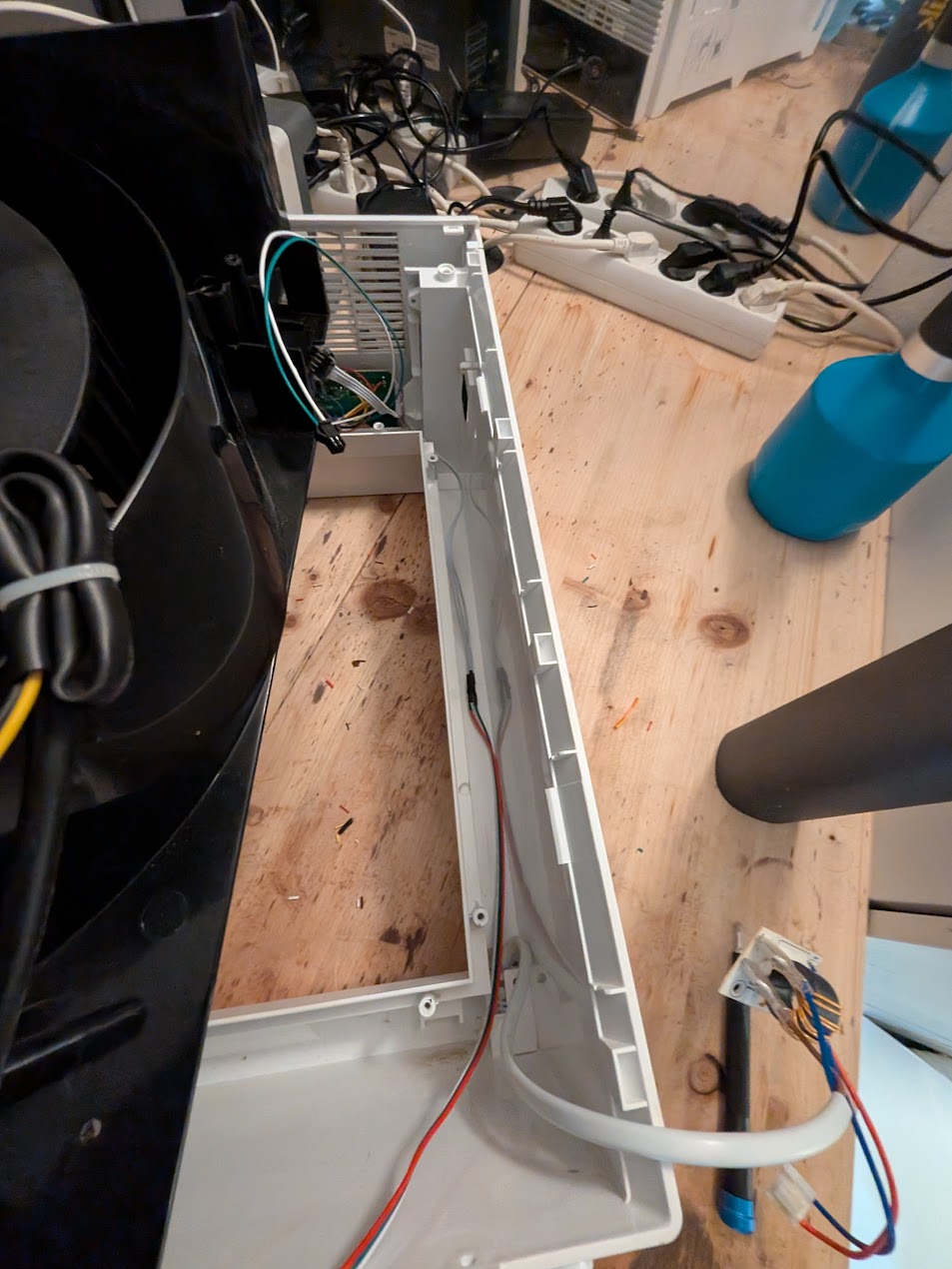
Assembly
-
Connect the new MCU to the PCB and secure with hot glue:
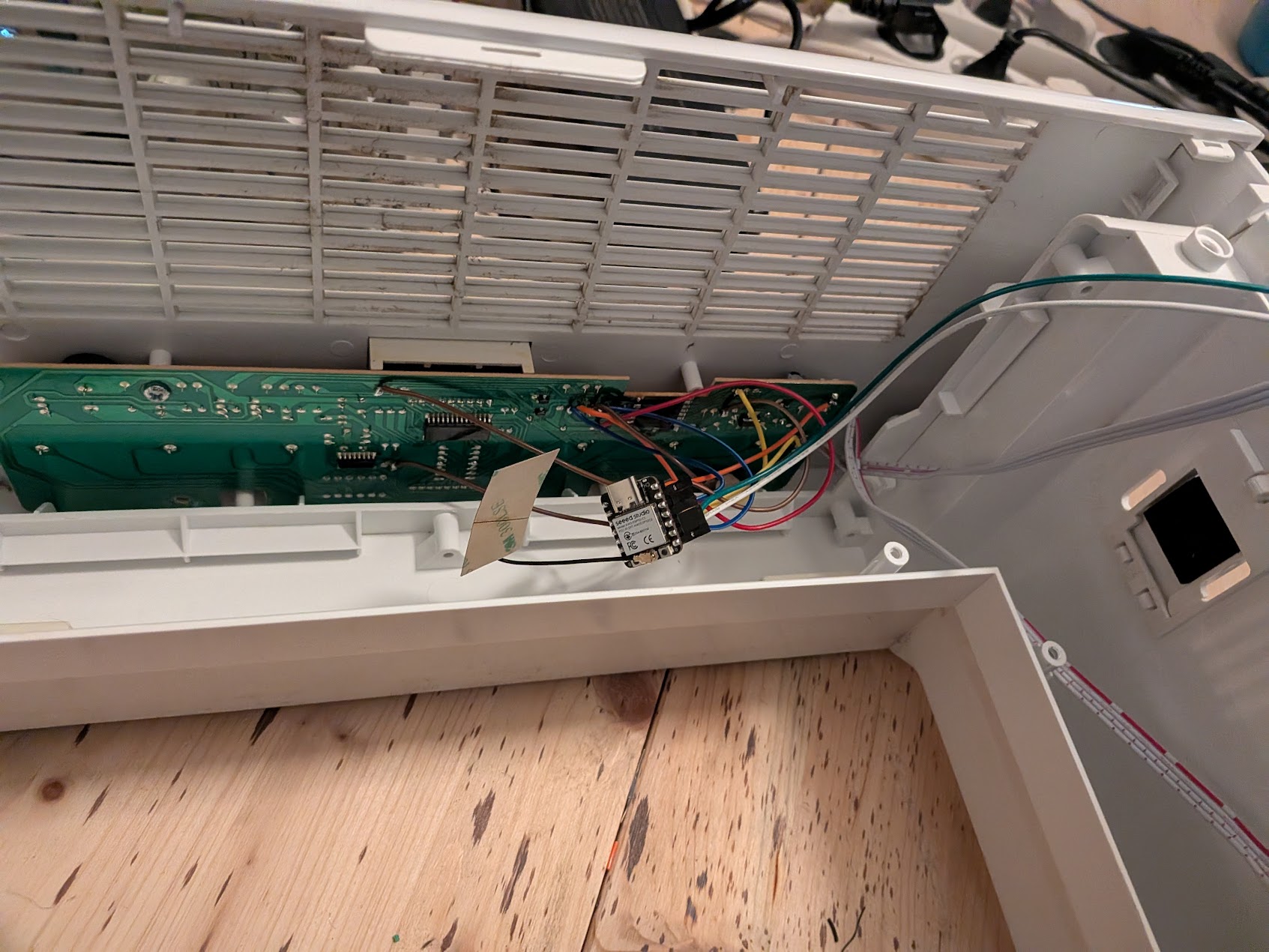
-
Position cables correctly: bottom cable on right side, sensor cables at top
-
Carefully insert the fan unit—ensure it sits fully at the top and no cables are pinched
-
Connect the MCU back to power board and verify power connections
-
Close the rear lid and screw in all fasteners
Done! Your upgraded LV-PUR 131S is ready for use.
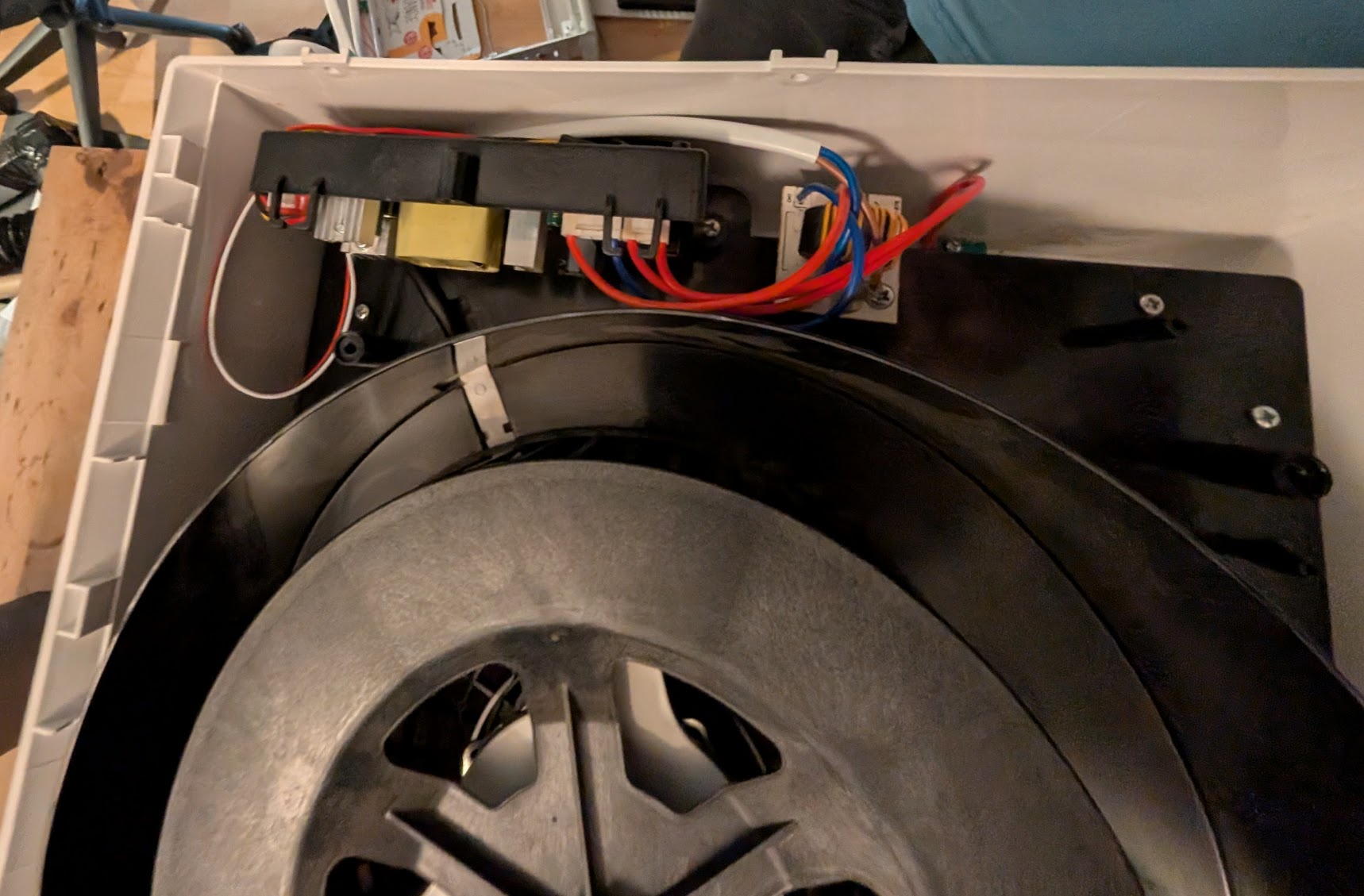
Hardware
Not like the other Levoits i have, only uses one ESP12F and no 2nd MCU
MCU: ESP12F
Fan / Main Power: 24V DC PCB: 5V
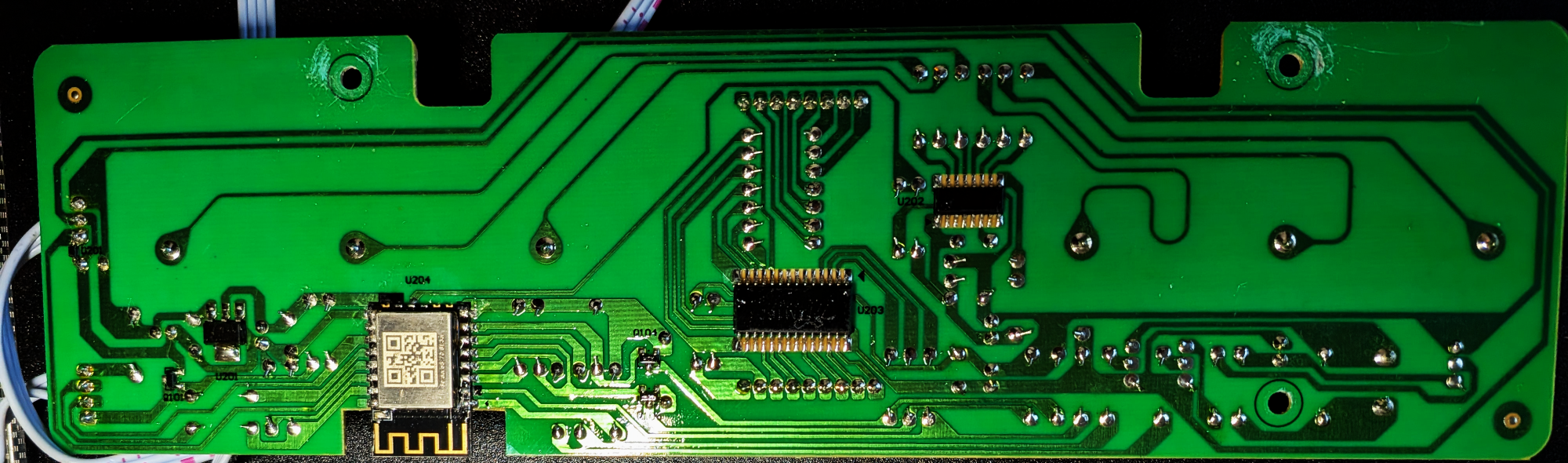
PCB
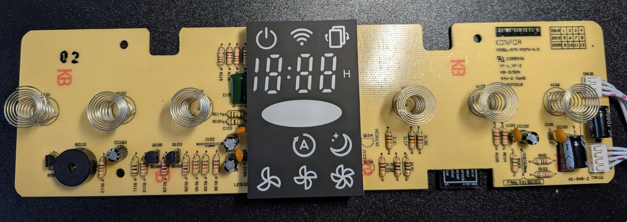
TODO add fried version!
ESP12F Pinout
Display driver - TM1628
SPI 500khz/ 1mhz?, 8 Bits, LSB Mode 0, enable active low
DIO -> GPIO13 SCK -> GPIO14 STP -> GPIO15
Command 1# 0x03 // 7 grids, 11 segs
Command 2# 0x40 // mode normal + increment + write
Command 3# 0xC0 //set adr
14 bytes data Command 4# 0x8C
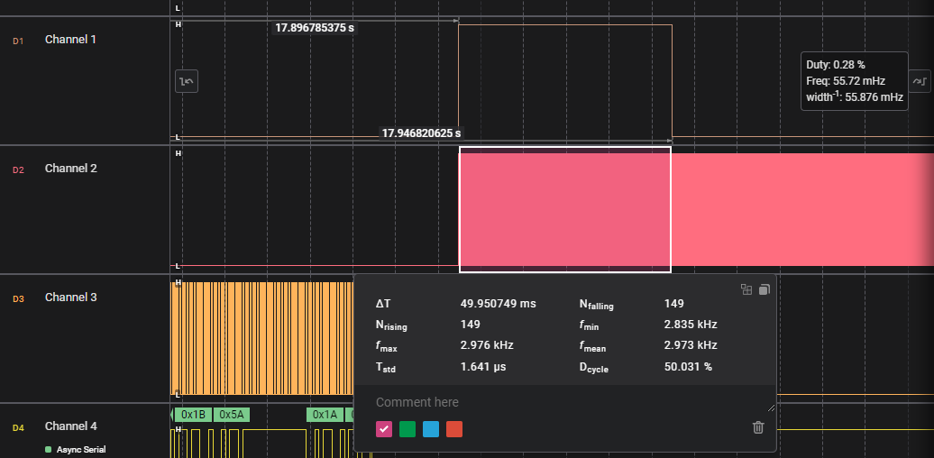
Buttons to Serial - ????
RX -> GPIO10 990 Baud 7 Bit 1 Stop bit, no parity, LSB
Start cmd: 0x1A 2 bytes Btn idx 2nd byte differs on release! sometime -> ignore! 15 ms between sends while presses
| Button | B1 | B2 | What |
|---|---|---|---|
| BTN1 | 0x1B | 0x5A | power |
| BTN2 | 0x1B | 0x53 | display |
| BTN3 | 0x1B | 0x5B | sleep |
| BTN4 | 0x5B | 0x5A | auto |
| BTN5 | 0x5B | 0x53 | Fan |
| BTN6 | 0x5B | 0x52 | timer |
PM1003
PWM/AQI -> GPIO03 Reset -> GPIO02 (pulled high? oin press connect to gnd)
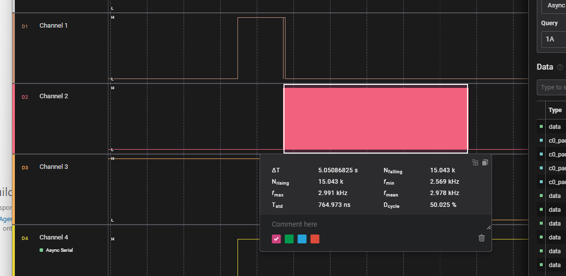
Fan - PWM out
GPIO04 3Khz, 2.976Khz
| Speed | Duty cylce |
|---|---|
| LOW | 40% |
| MID | 60% |
| HIGH | 80% |
Beep
uses 2 pins, one sends short on sig, 2nd provides freq => nice after hall effect ;)
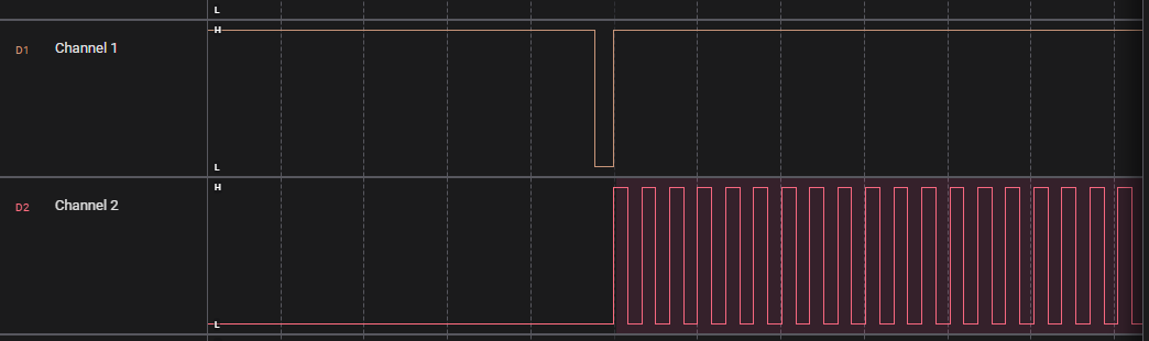
GPIO16 -> high 1.25s,low 220us, high 50ms GPIO12 -> PWM 2.975MHZ, 50%, starts after 220us low to high, contiunes for 5sec after start
Display Bytes Map
b[byte 0-13].[bit map]
b1.0x20 => 0x00 0x20 ….
Power:
b3.0x01 (top)
b3.0x02 (bottom)

=> 0x00 00 00 03 00 00 00 00 00 00 00 00 00 00
Wifi
b4.0x80 (top)
b5.0x01 (top)
Filter
b5.0x02
b13.0x02
Digits
  ---A---
 |       |
 F       B
 |       |
  ---G---
 |       |
 E       C
 |       |
  ---D---   • DP
| Digit | Segments On | Binary | Hex | | —– | ————- | ——– | —- | | 0 | A B C D E F | 00111111 | 0x3F | | 1 | B C | 00000110 | 0x06 | | 2 | A B D E G | 01011011 | 0x5B | | 3 | A B C D G | 01001111 | 0x4F | | 4 | B C F G | 01100110 | 0x66 | | 5 | A C D F G | 01101101 | 0x6D | | 6 | A C D E F G | 01111101 | 0x7D | | 7 | A B C | 00000111 | 0x07 | | 8 | A B C D E F G | 01111111 | 0x7F | | 9 | A B C D F G | 01101111 | 0x6F |
1(only 2 segs), 2, 3, 4 (7 segs)
Digit 1
only F and E!
F: b0.0x80
E: b1.0x01
Digit 2
byte 0
A: b0.0x01
B: b0.0x02
C: b0.0x04
D: b0.0x08
E: b0.0x10
F: b0.0x20
G: b0.0x40
Digit 3
A: b2.0x01
B: b2.0x02
C: b2.0x04
D: b2.0x08
E: b2.0x10
F: b2.0x20
G: b2.0x40
Digit 4
A: b4.0x01
B: b4.0x02
C: b4.0x04
D: b4.0x08
E: b4.0x10
F: b4.0x20
G: b4.0x40
Digits Dots
b1.0x04
Digits H
b10.0x20
Color:
3 colors, 8 leds in 2 rows per color
b6.01 r  [x   ]
b6.08 r  [ x  ]
b6.40 r  [  x ]
b7.02 r  [   x]
b8.04 r  [x   ]
b8.20 r  [ x  ]
b9.01 r  [  x ]
b10.02 r [   x]


b6.02 g  [x   ]
b6.10 g  [ x  ]
b6.80 g  [  x ]
b8.01 g  [   x]
b8.08 g  [x   ]
b8.40 g  [ x  ]
b9.02 g  [  x ]
b10.04 g [   x]


b6.04 b  [x   ]
b6.20 b  [ x  ]
b7.01 b  [  x ]
b8.02 b  [   x]
b8.10 b  [x   ]
b8.80 b  [ x  ]
b10.01 b [  x ]
b10.08 b [   x]


RED -> all red bits
b6.49
b7.02
b8.24
b9.01
b10.02

blue
b6.24
b7.01
b8.92
b10.09

yellow:
DB 02 6D 03 06 00 00 00 => Yellow

b6.db
b7.02
b8.6D
b9.03
b10.06
Auto
b11.0x02
b12.0x01
Sleep
b12.0x02
b12.0x04
Fan Low
b12.0x08
b12.0x10
Fan Mid
b12.0x20
b12.0x40
Fan High
b12.0x80
b13.0x01
Colors used by original Firmware
AQI
00 00 00 00 00 00 49 02 24 01 02 00 00 00 => RED
00 00 00 00 00 00 DB 02 6D 03 06 00 00 00 => Yellow
00 00 00 00 00 00 24 01 92 00 09 00 00 00 => blue


AQI RED
00000000 00000000 00000000 00000000 00000000 00000000 01001001 00000010 00100100 00000001 00000010 00000000 00000000 00000000

AQI YELLOW
00000000 00000000 00000000 00000000 00000000 00000000 11011011 00000010 01101101 00000011 00000110 00000000 00000000 00000000

AQI BLUE
00000000 00000000 00000000 00000000 00000000 00000000 00100100 00000001 10010010 00000000 00001001 00000000 00000000 00000000